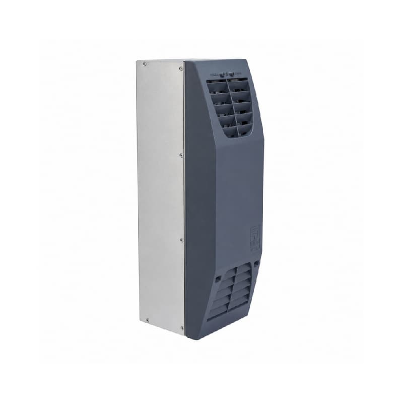
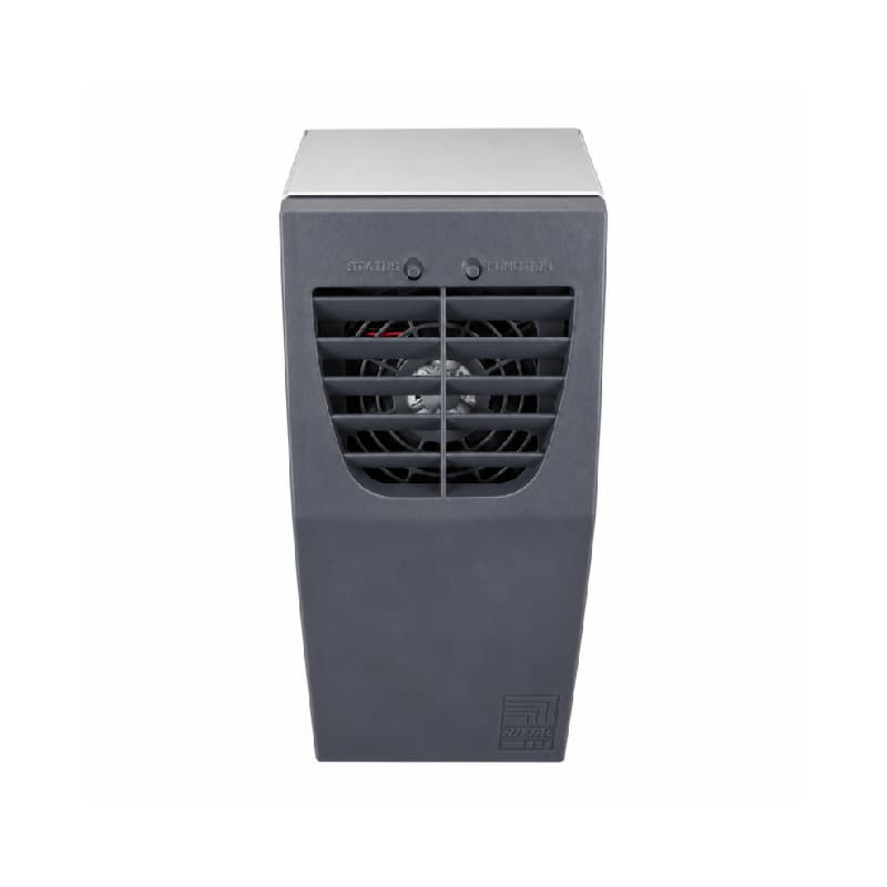
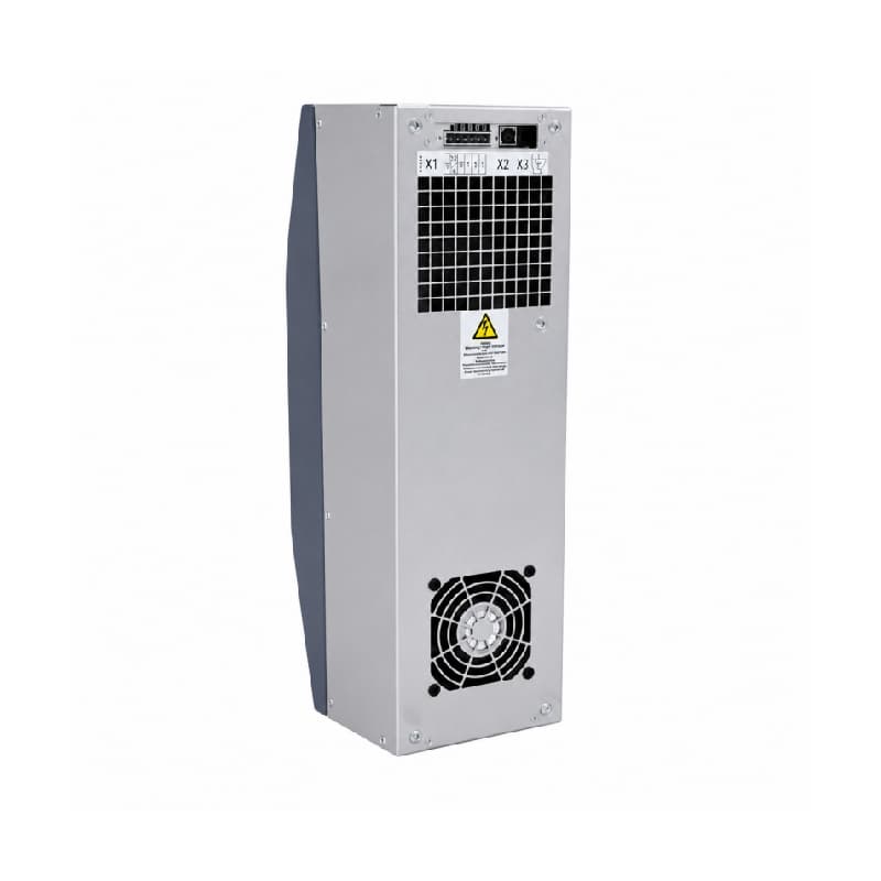
A PLC control cabinet can become much hotter than the surrounding plant. PLCs, power supplies, drives, industrial computers, and network equipment release heat, while a sealed enclosure limits natural heat loss. Components may then derate, age faster, trip, or cause an unplanned shutdown.
A thermoelectric cooler (TEC) can remove enclosure heat when space is limited, outside air is contaminated, refrigerant cooling is impractical, or both cooling and heating are required. It is not right for every cabinet: useful output depends on heat load, ambient temperature, required temperature difference, power supply, and hot-side heat dissipation.
This guide explains the engineering, compares alternatives, and provides a practical selection process.
What Is a Thermoelectric Cooler?
A thermoelectric cooler is a solid-state heat pump. Its core is a semiconductor module containing pairs of p-type and n-type thermoelectric elements connected electrically in series and thermally in parallel. When direct current passes through these elements, heat is absorbed at one face of the module and released at the other. This phenomenon is called the Peltier effect.
A TEC does not “create cold air.” It transfers heat from a cold side to a hot side:
- The cold side faces the cabinet interior and absorbs heat from recirculated internal air.
- The hot side faces the surrounding environment and rejects that absorbed heat.
- Heat sinks and usually fans move heat between the module, the two air streams, and the ambient air.
- A DC power supply drives the semiconductor module and any DC fans or controls.
The separated air paths transfer heat without intentionally drawing dusty plant air through the cabinet. “Solid state” describes the Peltier module itself; a complete unit may still use fans that need unobstructed airflow.
How Does a Thermoelectric Cooler Work?
Each stage affects real-world capacity.
Step 1: DC current passes through the semiconductor elements
Applied DC voltage causes current to flow through the alternating semiconductor junctions. Charge carriers move thermal energy through the module. At one set of junctions, heat is absorbed; at the other, heat is released.
Voltage and current must remain within the specified range. More electrical power does not guarantee proportionally more cooling because higher current also creates resistive heat inside the module.
Step 2: The cold side absorbs heat from the enclosure
An internal heat sink spreads the cooling effect across a larger surface. An internal fan moves cabinet air over that heat sink, collects heat from PLCs and other equipment, and returns cooled air to the enclosure.
Blocked fan inlets, cable bundles, crowded DIN rails, or a poor return-air path can create hot spots even when nominal capacity appears sufficient. Sensors should represent the protected equipment rather than sit directly in the cold-air discharge.
Step 3: The hot side releases heat to the ambient environment
The external heat sink must reject both:
1. the heat removed from the cabinet
2. the electrical power consumed by the thermoelectric module.
This energy balance explains why hot-side design is decisive. If the external heat sink is dirty, its fan is obstructed, or hot exhaust recirculates into its inlet, hot-side temperature rises. As the temperature difference across the module increases, available cooling capacity falls.
Thermoelectric performance therefore depends on more than a nameplate output. Engineers must evaluate:
- supply voltage and available current
- internal cabinet heat load
- maximum ambient temperature
- required cabinet temperature
- the resulting temperature difference, or ΔT
- internal and external airflow
- mounting orientation and clearance
- the manufacturer’s capacity curve at the actual operating condition.
Maximum temperature difference under little or no heat load is not useful enclosure capacity. Select by heat moved at the required ΔT.
Why Use Thermoelectric Cooling for Industrial Control Cabinets?
It can cool a closed cabinet in dusty environments
A basic filter-fan system exchanges cabinet air with plant air. Filters reduce contamination, but they add airflow resistance and require inspection or replacement. In facilities with conductive dust, fibers, oil mist, or corrosive contaminants, bringing outside air into the enclosure may be unacceptable.
A thermoelectric cooler uses separate air circuits, helping preserve a closed cabinet when its cutout, seals, and cable entries are installed correctly. The final protection rating still depends on the complete installation.
It fits compact equipment
TEC systems can suit small PLC cabinets, operator panels, machine-mounted enclosures, instrumentation boxes, and automation equipment where a compressor cooling unit would be oversized or physically difficult to install. Their useful range is generally low to moderate heat load; the actual limit must come from the selected model’s performance data.
It can provide heating as well as cooling
Reversing current polarity reverses heat transfer. With suitable controls, a reversible TEC can cool in hot conditions and heat in cold conditions. This helps outdoor cabinets and temperature-sensitive equipment exposed to wide ambient swings. It may support condensation control, but engineers still need temperature and humidity sensing, appropriate setpoints, and logic that avoids cooling below the dew point.
It reduces refrigerant-system complexity
The module has no compressor or refrigerant circuit, simplifying maintenance. Fans, heat sinks, seals, wiring, and controls still need correct installation and inspection.
Thermoelectric Cooler vs. Fan Cooling vs. Compressor Cooling
| Engineering factor |
Thermoelectric cooler |
Filter-fan cooling |
Compressor cooling unit |
| Heat-removal method |
Pumps heat through a Peltier module |
Exchanges warm cabinet air with cooler ambient air |
Uses a vapor-compression refrigeration cycle |
| Typical capacity position |
Low to moderate |
Depends on airflow and ambient-to-cabinet temperature difference |
Moderate to high |
| Can cool below ambient? |
Yes, within operating limits |
No |
Yes |
| Cabinet isolation |
High when correctly sealed |
Lower because outside air enters |
High when correctly sealed |
| Dust exposure |
No intentional outside-air exchange |
Depends on filter and maintenance |
No intentional outside-air exchange |
| Installation size |
Compact |
Compact |
Usually larger |
| Moving components |
No compressor; complete units commonly have fans |
Fan motor |
Compressor and fans |
| Maintenance |
Generally low; inspect fans, heat sinks, and seals |
Clean or replace filters; inspect fans |
Inspect filters, condenser, fans, drain, and refrigeration system |
| Efficiency at larger loads |
Usually less favorable |
Favorable when ambient air is cool and clean |
Usually more suitable for large cooling loads |
| Heating capability |
Possible by reversing polarity in a designed system |
No |
Model-dependent |
Choose a filter fan when ambient air is clean enough, the surrounding temperature stays below the allowed cabinet temperature, and air exchange does not compromise the enclosure. It is often the simplest option.
Choose a TEC when the load is modest, space is limited, cabinet isolation matters, and cooling below ambient or reversible heating is useful.
Choose compressor cooling when heat load is high, ambient conditions are severe, or the cabinet needs substantial continuous cooling. A TEC should not be specified merely to avoid a larger unit if it cannot provide adequate capacity and thermal margin.
How to Select the Right Thermoelectric Cooler
1. Calculate the cabinet heat load
Start with heat dissipated inside the enclosure, not total machine power. Use manufacturer heat-loss data for PLCs, power supplies, drives, industrial PCs, transformers, relays, and other devices. For a converter, its loss—not all power delivered to an external load—usually becomes cabinet heat.
Define realistic idle, normal-production, and peak-duty states. Apply simultaneous-use and duty-cycle assumptions only when supported by the machine sequence. Include planned additions and a margin appropriate to the consequence of overheating.
The cabinet may gain or lose heat through its surfaces. A simplified steady-state balance is:
Required cooling = internal heat dissipation + heat entering through the enclosure − useful passive heat loss
Heat-flow direction depends on ambient and target temperatures; outdoor designs must also include solar load. Use a recognized thermal-calculation method or manufacturer selection software rather than cabinet volume alone.
2. Define the worst-case temperatures
Record maximum ambient temperature at the cooler inlet, not the building average. Include nearby ovens, sun exposure, packed machines, and recirculated exhaust.
Set the highest acceptable internal temperature from the most restrictive component, its derating curve, sensor location, and reliability margin. The ambient-to-target difference affects available output, so a rating at one test condition may not apply at another.
3. Check the voltage and power requirement
Many automation systems use 24 V DC control power. Verify input range, maximum current, fan starting behavior, conductor size, circuit protection, grounding, and power-supply reserve. Do not assume the PLC supply has spare capacity.
For panels built around 24 V control power, the 24V DC Thermoelectric Cooler for PLC Control Cabinets is a relevant configuration to review. Confirm its current demand, performance curve, environmental rating, and control interface against the panel design before specifying it.
4. Match useful cooling capacity to the design point
Compare required cooling with manufacturer capacity at the calculated ambient and target temperatures. Allow for uncertainty, aging, fouling, supply variation, altitude if relevant, and imperfect airflow without arbitrary oversizing.
For a compact enclosure with a calculated moderate load, the 80W Cooling and Heating Thermoelectric Cooler may be a candidate. “80 W” must still be checked at the application’s actual ΔT and heat-rejection condition; it is not a promise that every cabinet dissipating 80 W will meet its target temperature.
5. Verify mechanical and environmental integration
Before ordering, check:
- Mounting requirements: Verify the mounting cutout, cooler dimensions, and required installation clearances.
- Airflow design: Ensure that the internal supply and return-air paths are unobstructed.
- Heat-dissipation space: Maintain adequate separation between the external air intake and exhaust to prevent hot-air recirculation.
- Mechanical compatibility: Confirm that the cabinet door or wall can support the cooling unit under expected vibration and operating conditions.
- Enclosure protection: Verify seal compatibility and ensure that the completed installation maintains the required enclosure protection rating.
- Installation position: Follow the manufacturer’s specified mounting orientation.
- Operating environment: Evaluate ambient temperature, humidity, dust, oil mist, chemicals, washdown exposure, and corrosion risk.
- Condensation control: Assess whether internal surfaces could fall below the dew point. Where necessary, provide suitable temperature control, humidity management, insulation, or manufacturer-approved condensate drainage.
- Maintenance access: Allow sufficient access for inspecting and cleaning fans, heat sinks, seals, and other serviceable components.
After installation, test the complete cabinet under realistic maximum-load and ambient conditions. Once the system reaches thermal equilibrium, record the internal and ambient temperatures, supply voltage, humidity, cooler operating status, and temperatures near critical components. Confirm that the cabinet remains within its specified temperature range and that no local hot spots or condensation develop.
Common Problems After Installing a Thermoelectric Cooler
Cooling performance is lower than expected
Common causes include an underestimated heat load, selection from a nominal rating at the wrong test condition, excessive ambient temperature, inadequate power, blocked internal airflow, or poor external heat dissipation. Check hot-side inlet and exhaust temperatures as well as cabinet temperature. A very hot external heat sink is evidence that heat is reaching it, but it may also show that the heat cannot escape effectively.
Condensation forms inside the cabinet
Condensation can occur when any internal surface falls below the local dew point. The risk depends on temperature and humidity, not temperature alone. Avoid unnecessarily low setpoints, monitor humidity, insulate or manage cold surfaces where appropriate, and use staged cooling/heating or anti-condensation control. If moist air can enter through doors or cable entries, correct those paths too.
The hot-side temperature keeps rising
The hot side rejects more heat than the cabinet heat load because it also releases the module’s electrical input. Maintain the specified external clearance, prevent exhaust recirculation, remove dust from heat sinks, verify fan direction and operation, and avoid mounting the unit where another machine heats its intake air.
The cabinet still has local hot spots
Average cabinet temperature can look acceptable while a drive or industrial PC inlet remains too hot. Rework component spacing, segregate high-loss equipment, route cables away from airflow, add internal circulation where justified, and place sensors near critical equipment without exposing them directly to cold discharge.
The unit cycles too often
Rapid cycling may indicate narrow control differential, poor sensor placement, excess capacity, or cold supply air reaching the sensor. Configure hysteresis and minimum on/off times appropriately.
Industrial Thermoelectric Cooling Solutions for Electrical Enclosures
An industrial TEC should be selected as part of the enclosure system, not as an isolated component. Engineers need to align enclosure size, internal losses, ambient temperature, required ΔT, voltage, cooling capacity, airflow, protection requirements, control strategy, and condensation risk.
Suwi’s Industrial Thermoelectric Cooling Solutions for Electrical Enclosures page presents 80 W cooling/heating configurations for command panels and small enclosures. Use the product rating as the start of verification, then request the applicable performance curve and confirm the complete installation against the design conditions.
FAQ
Q1:How does a thermoelectric cooler work
A: A thermoelectric cooler uses the Peltier effect. DC current passes through semiconductor junctions, causing one side to absorb heat and the other to release it. In an enclosure cooler, the cold side removes heat from recirculated cabinet air, while the hot side and its heat sink reject that heat to the surrounding environment.
Q2: Can a thermoelectric cooler cool a PLC cabinet?
A: Yes, if its useful cooling capacity at the design temperatures exceeds the calculated cabinet heat load with an appropriate margin. It is commonly considered for compact, closed PLC cabinets with low to moderate heat loads. High-load drive cabinets may require compressor cooling or another higher-capacity method.
Q3: Is a thermoelectric cooler better than a fan?
A: It depends on the application. A filter fan is simple and efficient when ambient air is cooler than the cabinet target and contamination is acceptable. A TEC can cool below ambient and maintain separated air circuits, but it consumes more power and has limited capacity. Dust protection, heat load, ambient temperature, maintenance, and enclosure requirements should drive the decision.
Q4: What voltage do industrial thermoelectric coolers use?
A: Industrial TEC units are available for different supplies. Many automation applications use 24 V DC because it matches common control-power systems. Always verify the exact input range, current demand, circuit protection, and available power-supply capacity for the selected unit.
Conclusion
A thermoelectric cooler moves heat; it does not generate an unlimited source of cold air. Its cold side absorbs enclosure heat, and its hot side must release that heat plus the electrical energy consumed by the module. That makes heat rejection, ΔT, and airflow just as important as the headline cooling rating.
TEC cooling is a strong candidate when the enclosure is compact, the heat load is moderate, dust protection matters, refrigerant-system complexity is undesirable, or heating and cooling are both needed. It is a poor substitute for a high-capacity compressor unit when the thermal load or ambient temperature exceeds its operating envelope.
Successful selection comes down to four items: calculate the heat load, define the worst-case ambient and target temperatures, check capacity at that design point, and verify the finished cabinet through measured thermal testing. Doing those steps before purchase is the most reliable way to obtain the expected result after installation.