
Get a Free Quote
If you are interested in our products and want to know more details,please leave a message here,we will reply you as soon as we can.

A control cabinet is not ready to order simply because every component fits on the mounting plate. Once the cabinet is wired and installed on the machine, a connector may sit too close to the door, an operator panel may obstruct loading, or a drive may be impossible to remove without disturbing the equipment beside it.
SUWI’s position is that enclosure selection should be checked against the assembled cabinet in use. The question is not only whether the equipment fits, but whether it can be connected, operated, cooled and replaced in its intended location.
This changes the order of the selection process. Establish the component layout and its connection and service spaces first, compare enclosure arrangements against those needs, then release the cabinet configuration and drawings for purchasing. Choosing the smallest available body before those checks can move cost from purchasing into assembly and maintenance.
The following sections explain where that trade-off matters for CNC, packaging machinery and automation equipment manufacturers.
Start with the proposed cabinet position rather than the machine category. Two CNC machines may need different arrangements if one cabinet stands outside the machining area and the other is exposed to coolant during operation or cleaning. Record the conditions at that location, including access during loading, changeovers and maintenance.
| Machine Type | Condition That Changes the Selection | Configuration Decision |
|---|---|---|
| CNC and metalworking | Exposure to chips, coolant spray or oil mist; loading equipment passing near the cabinet or terminal. | Check whether a different location reduces exposure without extending cable routes or restricting service access. Assess sealing and cooling for the location retained. |
| Packaging machinery | Dry cleaning, wet cleaning or washdown; access needed for material replenishment and format changes. | Define the cleaning conditions before selecting the enclosure and fittings. Check that the terminal and cabinet doors leave the required changeover routes usable. |
| Automated assembly and inspection | Distributed devices, long connection routes or defined future station additions. | Compare central and local installation using cable routes, connection access and replacement tasks. Reserve space for identified additions rather than an arbitrary spare-space percentage. |
For a cabinet exposed to cleaning spray, SUWI would first examine whether its position can be changed without creating another access problem. If relocation is impractical, the enclosure, seals, entries and cooling arrangement need assessment for the stated exposure. Stainless steel alone does not settle that decision. Rittal’s hygienic design comparison explains why material choice and hygienic enclosure design are different questions.
Build the layout around the installed connections as well as the component bodies. Use the selected devices’ drawings to include plugs, cable bends, mounting access and required installation clearances. Also show how the largest serviceable items leave the cabinet. A device outline alone understates the space the assembly uses.
An AX compact enclosure, a freestanding control cabinet and a VX25 baying enclosure system are arrangements to compare against that layout. Confirm usable dimensions and accessory compatibility for the exact article numbers before treating any option as a fit.
Hypothetical example: a drive connector meets the closed door. Check the mounting plate position, drive projection, fully seated plug, cable bend requirement and the nearest door-mounted obstruction. Then check the separate distance needed to release and withdraw the plug with the door open. If moving the drive into a clear area resolves both conditions, revise the layout. If the depth conflict remains wherever the drive can reasonably be installed, assess a deeper enclosure before ordering.
A smaller cabinet can still be the better purchase when the connections and replacement paths remain accessible. Its lower purchase price becomes less persuasive if routine wiring requires awkward assembly sequences, or replacing one device requires disconnecting several others. For a repeated machine build, compare the enclosure price difference with the estimated additional assembly work and the agreed maintenance procedure. Treat those estimates as project inputs, not as a general claim that a larger cabinet always costs less overall.
Release check: identify whether the unresolved constraint is width, height, depth or access. Change the enclosure arrangement to address that constraint, then recheck the assembled layout.

A terminal position has to work for three different activities: operating the machine, moving material and removing the equipment for service. Checking only the screen height can miss the other two. Mark the operator’s normal position and required view, then overlay the loading route, guard movement and terminal removal path.
Where a fixed housing gives a good operating view but blocks a loading route, first assess a different mounting position. A support arm is an alternative only if its movement, load capacity and cable route work for the machine. Adding movement without checking the swept area may simply make the obstruction movable.
Before accepting either arrangement, trace the replacement task: release the clamps, unplug the cables and withdraw the device. If the machine frame blocks that path, increasing the housing size may not help. Revise the mounting position or removal arrangement before releasing the terminal configuration.
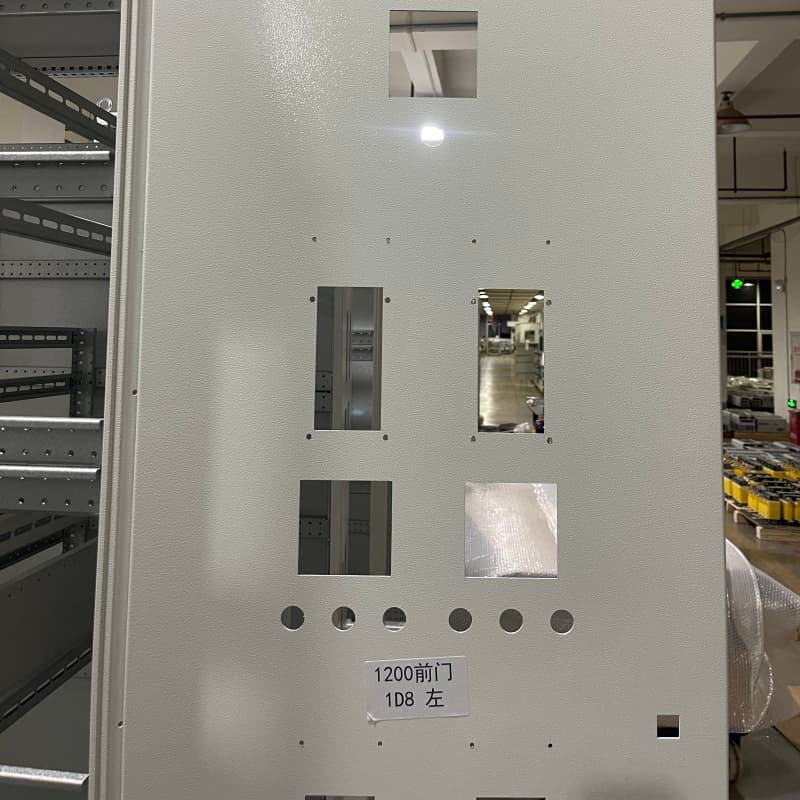
A machining drawing describes the opening; the internal installation drawing shows whether that opening can be used. Review them together, with the same viewing direction and reference edges. Include the device body, fixing holes, gasket contact area, clamps, ducts, rails and cabinet framing on both sides of the proposed position.
Hypothetical example: an HMI opening is clear on the door drawing, but its rear clamp overlaps a wiring duct. Compare the mounting template with the internal layout. If the duct can move without compromising the wiring route or other clearances, revise its position. If not, assess moving the opening or changing the device arrangement. Issue the machining and assembly revisions together; changing only one leaves conflicting instructions for production.
Apply the same review to cooling cut-outs and cable entries. An opening that can be machined accurately may still leave no room for a rear fitting or installation tool. List the required enclosure accessories by exact article number and verify both compatibility and scope of supply. Do not assume that a part included with one configuration is included with another.
Use component heat-loss data for the expected load and duty cycle, rather than motor output ratings. Establish the temperature expected at the installed cabinet, the permitted internal temperature, contamination and cleaning conditions. Then check whether the proposed layout leaves the selected cooling equipment’s required airflow paths and service access available.
| Cooling Method | Selection Check |
|---|---|
| Natural heat dissipation | Assess the heat load, temperature difference and exposed surfaces using an applicable manufacturer calculation method. If the resulting internal temperature exceeds the design limit, assess additional cooling. |
| Filter fans | Consider where ambient air is sufficiently clean and cooler than the required internal temperature. Check model-specific airflow, filter access and protection requirements before selecting the arrangement. |
| Air-to-air heat exchangers | Consider separate air circuits where direct air exchange is unsuitable. Verify output at the actual temperature difference; this method does not provide cooling below ambient temperature. |
| Enclosure air conditioners | Where the thermal assessment rules out ambient-air methods, assess a suitable unit using its capacity data and operating limits. Include condensate provisions, mounting clearances and maintenance access. |
An unchanged cabinet model does not establish an unchanged cooling requirement. Additional drives, different operating duty, a warmer installation position or reduced exposed surface area can change the thermal assessment. A revised internal layout also deserves review where it alters the cooling equipment’s airflow paths. Different cleaning or contamination conditions may change which cooling method is suitable.
For a repeat machine, compare those inputs with the previous assessment before carrying over the cooling model. Reuse is reasonable where the review supports the existing selection; it should not depend on the enclosure number alone. If the cooling unit or its position changes, recheck the cut-out, fixings and rear clearance before reusing the machining drawing.
For the next selection step, see Choosing the Right Cabinet Cooling Method or compare enclosure climate control products against the defined application inputs.
Manufacturer reference: Rittal ambient-air cooling and air-to-air heat exchangers. Use the selected model’s technical data and installation instructions for final verification.

For batch-built machines, a common enclosure can simplify purchasing, but only if the differences between machine versions remain explicit. SUWI’s approach is to retain a reviewed common configuration where it works, then identify the parts and drawings that change by machine version. A shared cabinet number should not conceal different HMI openings, cable entries or cooling equipment.
Standardising on one cabinet size is useful where it accommodates the intended variants without unresolved access or thermal compromises. Where one variant needs a substantially different depth, opening pattern or cooling arrangement, a separate configuration may be clearer than a common body with poorly controlled exceptions. Make that decision using the actual layouts and supply differences.
Worked review example: the cabinet article number has not changed, but the HMI has.
This is a hypothetical example, not a report of a completed SUWI project. The new HMI has a similar visible screen size. That is insufficient evidence for reusing the old machining drawing.
The same change review applies to a new gland plate, cooling unit or door-mounted accessory. Check the opening dimensions, fixing pattern, sealing area and internal obstructions. The unmodified enclosure’s protection rating alone does not verify the completed modified arrangement.
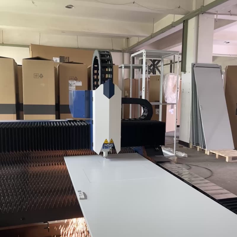
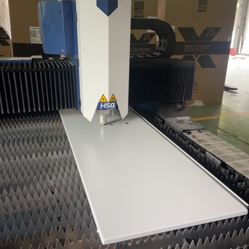
For drawing-based enquiries, the enclosure customization and accessory verification services page provides a starting point. The quotation should identify the actual panels, operations, supplied parts and drawing revisions rather than relying on a general service description.
A: Yes. Mark the enquiry as preliminary and identify the unresolved models or dimensions. Ask which assumptions affect the quoted configuration. Before release, replace those assumptions with reviewed information or an explicitly agreed design basis.
A: Request the exact article number and supporting documentation. Review the mounting interface, usable space and any effect on loads, sealing or machining. If accepted, update the BOM so the approved substitution is visible to purchasing and assembly.
A: Not necessarily. Shared drawings can work where a variant schedule unambiguously identifies the applicable parts and operations. Use separate drawings where options overlap, exclusions become difficult to follow or the supplier could reasonably machine the wrong version. Ask the supplier to confirm that the released package identifies one buildable configuration.
A: Identify the affected order and revisions, then confirm production status with the supplier. Review mounting, connections, heat loss and access before issuing the change. Agree which revised documents apply and how any work already completed will be handled.
Submit enough information to identify the assembled arrangement and the supply scope:
Before ordering, reconcile the quotation with the BOM and drawing set. Confirm what is included, what is supplied separately, which panels are machined and which revisions govern the work. Mark preliminary documents clearly so they cannot be mistaken for a manufacturing release.
Drawings and BOMs can be emailed to suwiauto@gmail.com. State whether the enquiry concerns an initial comparison, a quotation or a repeat configuration, and identify the decisions still open.
For supplier information, see company information, Rittal authorization documents and scope and the current service description. Confirm the scope relevant to the proposed order in the quotation.